Introduction
Overview
This document will overview the process of configuring SSIDs bound to separate VLANs on a DD-WRT access-point
Disclaimer
I am in no way affiliated with the DD-WRT project, nor with Asus. DD-WRT may work on your device, or may cause issues. The following is a guide only, and may not work for you exact situation. Reflashing a device may lead to failure, "bricking", unexpected errors, or other issues, and I cannot guarantee that the process described will work for you. By continuing, you agree that to be solely responsible for any potential damage to your router or other attached devices.
But Why?
Why might you want to do this?
The common usage is to create SSIDs which are all broadcast from the same physical router/access-point connected but are logically separate from each other. This could allow you to create a layer of separation between your wireless devices
No really, why? (examples)
Some examples of where you might have separate SSIDs include:
- Devices may talk to services on your local LAN
(i.e. a trusted wifi network) - Devices may only talk to the Internet
(i.e. for a Guest Wifi network) - Device devices may talk to some portion of your network but not to the internet
(useful for a local IoT network) - Devices may only talk to a proxy, or a restricted list of destinations
(useful for restricting/monitoring access to only trusted destinations, possibly for a kids' network) - Devices may only talk to a restricted subset of the network, or restricted services
(i.e. for a QA/testing network, etc etc) - Devices may only talk through a VPN, when established
- etc
The actual limit of SSIDs/VLANs depends on the capabilities/limits of your hardware and current version of DD-WRT etc
By using VLANs, you can use a single physical connection between your DD-WRT AP and your firewall
The Device
Our example device is an Asus AC1900 (RT-AC1900P) router.
Getting DD-WRT
The first thing to do with your device is check whether it's actually supported for DD-WRT.
Check here
If there is a minimum build # listed, your device should support DD-WRT. If it's a WIP... then it may require special steps or the build may not be fully functional.
Please note that the list is not exhaustive, and will in fact point you at the forums for more up-to-date information (but it's a good place to start)
Some devices have a link to an install guide, so follow that as needed.
The latest beta builds can be found here
For our device, there are still regular builds. Find the sub-folder for the current year, followed by the latest month/day and build # Grab the current .TRX firmware file
Installing DD-WRT
In the case of the RT-1900P, I was able to upload the firmware via the standard Asus WebUI. Doing so, however, put the router into rescue mode. In this mode, the device does not provide a DHCP server and has a limited web interface.
You can also force rescue mode by holding the RESET button (indent at the back) while the device is powered off, then continuing to hold it for approx 20s while you power the device on. In this mode, the power LED will blink on and off
Rescue Mode
To access your device while it is in rescue mode, you will need to:- Connect an Ethernet cable from port 1 of the router to a PC or laptop
- Manually set the (wired) IP address of your PC to 192.168.1.2, with a subnet of 255.255.255.0 (/24)
- Ensure that the above does not overlap any connected wireless network (or disconnect wifi, as applicable)
- From a browser on your PC, navigate to http://192.168.1.1
You should end up at a screen like the following:
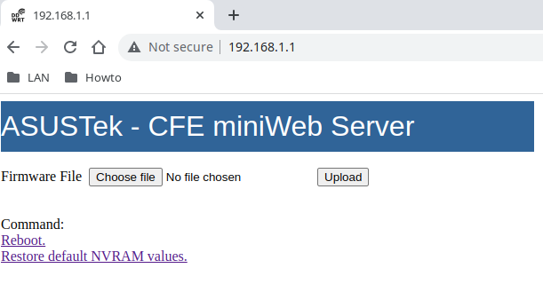
You can use the "Choose file" button to select new firmware from your PC, then click Upload to load it into the router.
This will take a few moments and you should see a screen like
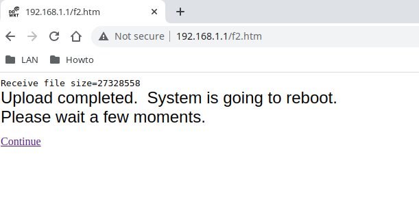
If this was the first time flashing the device with DD-WRT, you will likely need to re-enter rescue mode and click the "Restore default NVRAM values"
Now click the "Reboot" link. Wait for the device to finish rebooting before you hit continue (you can watch to see when it returns a PING)
The initial loading process may take a few moments.
Accessing DD-WRT
If things are flashed correctly, you should be able to get a DHCP-assigned IP address. By default the router will also likely using 192.168.1.1 so you could continual with the manual assignment, but I recommend switching back to DHCP at this point
Access the router via the webpage at http://192.168.1.1
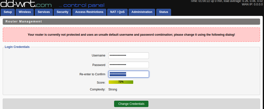
Set the administrative password
You should be at a password change screen. Set your administrative username and a good password (it should not be the same as your wifi password) and click "Change Credentials"
Some Base Configuration
Click on the "Setup" button.
You will be prompted to enter your username and password. Enter the ones you configured earlier. If you messed up on these somehow and locked yourself out... reset the device back to Rescue Mode and restore the default NVRAM values, again.
About our Configuration
In this example configuration, we will be setting up 4 SSIDs which attach to 3 VLANs, and a seperate VLAN for the LAN connections:
- LAN network on VLAN 1
- Main Wifi network on VLAN 26 (dd-2.4g and dd-5g)
- A "guest" VLAN on VLAN 27 (dd-guest)
- An "IoT" VLAN on VLAN 55 (dd-iot)
In the example configuration, we are not using firewall or even routing capabilities of the device. It will function purely as an AP with SSIDs tied to the various VLANs.
In this example configuration, each of these VLANs would lead to a networks with the own DHCP server, firewall, etc.
All networks will be connected through the WAN port on the DD-WRT device.
Your own configuration may diverge from this and you may want to use DHCP on some of the SSIDs and/or use the firewall.
While you are setting things up, you will probably want to keep the router unplugged from the rest of your network (don't plug in the WAN port either)
Wireless Tab

Basic Settings sub-tab
"Regulatory Domain" section- Set the "Domain" to your country
The main 2.4Ghz and 5Ghz SSIDs
These are your primary SSIDs which will be tied for VLAN 26 (internal wifi)
"Wireless Interface wl0" section- Radio Mode: AP
- Network Mode: Mixed
- Service Set Identifier (SSID): dd-2.4g
- Channel: Auto
- SSID Broadcast: Broadcast
- Web UI Access: Enable
- Network Configuration: Bridged
- Radio Mode: AP
- Network Mode: Mixed
- Service Set Identifier (SSID): dd-5g
- Channel: Auto
- SSID Broadcast: Broadcast
- Web UI Access: Enable
- Network Configuration: Bridged
Adding a 2.4Ghz Virtual "IoT" network and "conf" network
Beneath the 2.4Ghz (wl0) interface, find the "Add Virtual AP" button and click it.
This should create a new Virtual Interface wl0.1.
Click the same "Add Virtual AP" (under the 2.4Ghz wl0) button again
This should create a new Virtual Interface wl0.2
Configure these new virtual interfaces
- Service Set Identifier (SSID): dd-iot
- Web UI Access: Disable
- Network Configuration: Bridge
- AP Isolation: Enable
- Service Set Identifier (SSID): dd-conf
- Web UI Access: Enable
- Network Configuration: Bridge
- AP Isolation: Disable
The conf network can be deleted later, but at times during the VLAN and IP changes you may run into issues and this should be helpful to connect
Save, Apply Settings
Adding a 5Ghz "Guest" Network
Beneath the 5Ghz (wl1) interface, find the "Add Virtual AP" button and click it.
This should create a new Virtual Interface wl1.1.
Virtual Interface wl1.1- Service Set Identifier (SSID): dd-guest
- Web UI Access: Disable
- Network Configuration: Bridge
- AP Isolation: Enable
Save, Apply Settings
Wireless Security sub-tab
For each of the interfaces (wl0,wl0.1,wl1,wl1.1), set security mode (i.e. WPA2-PSK), WPA Algorithms, and WPA Shared Key (wifi password)
Save, Apply Settings
At this point, you may wish to connect via wifi to the "dd-conf" network. Make sure you fix your wireless IP to something in the 192.168.1.x network with a netmask of 255.255.255.0
Setup Tab

"Switch Config" sub-tab (VLANs)
This is the first section that really applies to the VLANs in question. If you are not using the same device as me, this section may look different and you may have more or less ports
- In the "Action" column, click the circled "+" to add each VLAN, until you have the following new VLANs
- 26
- 27
- 55
- Under the "Tagged" row", ensure that there is only a checkbox in the "WAN" Port column (not 1-4)
- Ensure the "Autonegotiation" row has a checkbox each Port column (WAN 1 2 3 4)
- Ensure the "Enabled" row has a checkbox for each Port column (WAN 1 2 3 4)
- Back up to the VLANs
- VLAN 1 should be checked for all port columns (WAN 1 2 3 4)
- The other VLANs (26,27,55) should be checked under the "WAN" Port column and no others
The end result will look something like this:
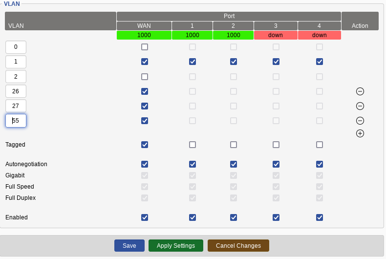
Make sure to "Save" and "Apply Settings"
"Networking" sub-tab (more VLAN config and bridging)
This section is a little persnickety so you may have to apply/reboot between some setting changes Tagging sub-section Add the following tagging:| Interface | Tag Number |
|---|---|
| eth0 | 1 |
| eth0 | 26 |
| eth0 | 27 |
| eth0 | 55 |
Bridging sub-section
Under this section, create the following bridges using the button in the "Action" column
- br-vlan1
- br-vlan26
- br-vlan27
- br-vlan55
Create the following configuration
| Assignment | Interface |
|---|---|
| br-vlan26 | vlan26 |
| br-vlan26 | eth1 |
| br-vlan26 | eth2 |
| br-vlan27 | vlan27 |
| br-vlan27 | wl1.1 |
| br-vlan55 | vlan55 |
| br-vlan55 | wl0.1 |
| br-vlan1 | vlan1 |
Note, due to some weirdness with DD-WRT and/or this device, wl0 is represented by eth1, and wl1 is represented by eth2
eth0 is an interface that is divided up into the ports via the switch configuration under the "Switch Config" tab
Interface Setup Port Setup sub-section- WAN Port Assignment: vlan1
- Label: LAN VLAN
- Label: Wifi VLAN
- Label: Guest VLAN
- Label: IoT VLAN
- Label VLAN1 bridge
- Net Isolation: Disable
- IP Address: (set this to an IP on your LAN to access for configuration)
- Label VLAN1 bridge
- Net Isolation: Disable
- IP Address: (set this to an IP on your Wifi network to access for configuration)
- Label VLAN1 bridge
- Net Isolation: Enable
- IP Address: (do not set)
- Label VLAN1 bridge
- Net Isolation: Enable
- IP Address: (do not set)
"Basic Setup" sub-tab
"WAN Connection Type" section- Connection Type: Depends on your network. If you have a DHCP server on your primary VLAN, stick with that
- DHCP Type: DHCP forwarder
- DHCP Server: (the actual IP of a DHCP server on your primary network) "NTP Client Settings" section
- Configure as appropriate for your device
"Administration" Tab

"Management" sub-tab
"Web Access" section- HTTP: Can be checked or unchecked. I recommend ensuring HTTPS works before unchecking this
- HTTPS: Check
- Web UI Managment: Enable
- Use HTTPS: Check
- Telnet Management: Disable
- Allow any remote IP: Can be Enabled, or you can specify a subnet with access
- Enable Button: Enable